Sunday, 18 November 2012

GPIO tutorial for ARM7TDMI (lpc2148):


General purpose input output (GPIO) is same thing you find in any microcontroller like 8051, avr etc.


Lpc2148 have two General Purpose I/O ports port 0 & port1.port0 & port1 both are 32-bit bi-directional ports like 8051 has four 8-bit bi-directional ports.


In port0,

P0.24, P0.26, P0.27 are not physically available means you can’t find them on chip but still you can write values to them. & P0.31 is available for digital output only.

Also this port has many alternate functions like 8051.


In port1,

P1.0 to P1.15 is not available physically. Only P1.16 to P1.31 is available.

So out of 64 pins 45 pins are covered by port0 & port1.


How to program ports?

Now let’s understand how to program these ports. There are 4 resisters you need to understand to access these ports

IOPIN
For port0 use IOPIN0 & for port1 use IOPIN1.you can also write IO0PIN & IO1PIN both things are same.

Function:
GPIO Port Pin value registers. The current state of the GPIO configured port pins can always be read from this register, regardless of pin direction.

IOSET
For port0 use IOSET0 & for port1 use IOSET1.again you can also write IO0SET & IO1SET both things are same.

Function:
GPIO Port Output Set registers. This register controls the state of output pins in conjunction with the IOCLR register. Writing ones produces highs at the corresponding port pins. Writing zeroes has no effect.
IODIR
For port0 use IODIR0 & for port1 use IODIR1.again you can also write IO0DIR & IO1DIR both things are same.

Function:
GPIO Port Direction control register. This register individually controls the direction of each port pin.

IOCLR
For port0 use IOCLR0 & for port1 use IOCLR1.again you can also write IO0CLR & IO1CLR both things are same.

Function:
GPIO Port Output Clear registers. This
Register controls the state of output pins. Writing ones produces lows at the
corresponding port pins and clears the
Corresponding bits in the IOSET register.
Writing zeroes has no effect.


Let’s understand some C program:


We will understand GPIO & register using some C program. First of all remember that header file for lpc2148 is “lpc214x.h” like reg51.h for 8051.


1) Blinking LED using IODIR, IOCLR, and IOSET:

My development board has an LED at P0.21 so we are going to use this LED for our example you can also run this program in Kiel debugger.


Program:
#include<lpc214x.h>
void wait(void)             //generate small delay
{int d;
for(d=0;d<1000000;d++);
}

int main(void)
{
IODIR0=0x00200000;  //set P0.21 as output port
while(1)
{
IOSET0=0x00200000;  //set p0.21
wait();
IOCLR0=0x00200000; //clr p0.21
wait();
}}


Explanation:


In this program first we select we select which pin will be output & which pin will be input by using IODIR0.remember 0=input,1=output.


Then we write 1(high) to that pin using IOSET0 register. Remember writing 0 to any bit of IOSET0 have no effect on port pin but writing 1 will produce high on corresponding port pin.


Then we write 0(low) to that pin using IOCLR0 register. Remember writing 0 to any bit of IOCLR0 have no effect on port pin but writing 1 will produce low on corresponding port pin.

Ok, here we complete our first program I know there may be lots of questions in your mind like why can’t we do P0=0x00200000,P0=0x00000000 as we do in 8051 and why we write entire word(32-bit data=word) why we can’t do sbit mybit P0^21 as we do in 8051.


So fact is that both of these things don’t work on ARM but there are ways to do something like that. Let’s see how to do this.

2) How to do sbit mybit P0^21 i.e. address a single bit rather addressing entire register.

First of all keep in mind that there is no keyword like “sbit” in ARM c programming. But we can do this by using “<<” operator. This operator shifts the value on its left side to left by 1 bit by the value specified on its right side.

So now suppose we want to produce 0x00200000 you can just write (0<<21) both will be same.


Program:

#include<lpc214x.h>
void wait(void)                                                    //generate small delay
{int d;
for(d=0;d<1000000;d++);
}

int main(void)
{
IODIR0=(1<<21);              //set P0.21 as output port
while(1)
{
IOSET0=(1<<21);              //set p0.21
wait();
IOCLR0=(1<<21);              //clr p0.21
wait();
}
}


3) how to do P0=0x00200000,P0=0x00000000.


Well there is no register like P0 ( 8051 ) in ARM. But there is a register called IOPIN0 which do very much similar task as P0.what ever value you write to IOPIN register will directly appear on physical pins. & you can also read IOPIN register to know the status on pins.


Program:

#include <LPC214X.H>
void wait()
{
int d;
for(d=0;d<1000000;d++);
}

int main()
{
IODIR0=0x00200000;
while(1)
{
IOPIN0 =0x00200000;
wait();
IOPIN0 =0x00000000;
wait();
}}


4) Let's try to read input also


Till now we have only seen output. But let’s include some input also. My development board has a button on P0.15 . So let's make a program in which LED will be turned on when there is high on P0.15 and when there is low on P0.15 LED will be off.


Program:

#include<lpc214x.h>
int main()
{
                IODIR0=(1<<21);
                IODIR0&=~(1<<15);
                while(1)
                {
                                if(!(IOPIN0&(1<<15)))
                                {
                                                IOCLR0=(1<<21);
                                }
                                if(IOPIN0&(1<<15))
                                {
                                                IOSET0=(1<<21);
                                }
                }
}


Thursday, 13 September 2012

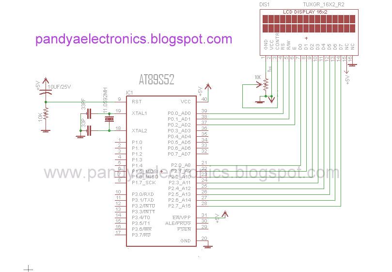
how to display moving message on 16x2 lcd

code:
#include<reg51.h>
sfr lcd_data_pin=0xA0; // data port P2
sbit rs=P0^0; // Register select pin
sbit rw=P0^1; // Read write pin
sbit en=P0^2; // Enable pin


void delay(unsigned int msec) //delay function
{
int i,j;
for(i=0;i<msec;i++)
for(j=0;j<1275;j++);
}


void lcd_command(unsigned char comm) // function to send command to LCD
{
lcd_data_pin=comm;
en=1;
rs=0;
rw=0;
delay(1);
en=0;
}


void lcd_data(unsigned char disp) // function to send data on LCD
{
lcd_data_pin=disp;
en=1;
rs=1;
rw=0;
delay(1);
en=0;
}

lcd_dataa(unsigned char *disp) // function to send string to LCD
{
int x;
for(x=0;disp[x]!=0;x++)
{
lcd_data(disp[x]);
}
}


void lcd_ini() //Function to inisialize the LCD
{
lcd_command(0x38);
delay(5);
lcd_command(0x01);
delay(5);
lcd_command(0x0C);
delay(5);
lcd_command(0x80);
delay(5);


}
void main()
{
lcd_ini();

lcd_dataa(" pandya"); //place your text
lcd_command(0xc0);
lcd_dataa("electronics");

while(1)                   //function that scroll the message
{
delay(100);
lcd_command(0x05);
}

}

Circuit Diagram:


PandyaElectronics' prototype:


check out video:

how to make a digital clock with 8051 and without RTC


code:

/******** simple clock with hour,minute & second **********
********************24 hour mode***************************
code from: www.pandyaelectronics.blogspot.com**************/


#include<reg51.h>
sfr lcd_data_pin=0xA0; // data port P2
sbit rs=P0^0; // Register select pin
sbit rw=P0^1; // Read write pin
sbit en=P0^2; // Enable pin


void delay(unsigned int msec) //delay function
{
int i,j;
for(i=0;i<msec;i++)
for(j=0;j<1275;j++);
}


void onesecond(void) //genrates accurate delay of one second
{
int i;
for(i=0;i<20;i++)
{
TL0=0xB0; //calculation made for 12Mhz crystal
TH0=0X3C;
TR0=1;
while(TF0!=1);
TR0=0;
TF0=0;
}
}


void lcd_command(unsigned char comm) // function to send command to LCD
{
lcd_data_pin=comm;
en=1;
rs=0;
rw=0;
delay(1);
en=0;
}


void lcd_data(unsigned char disp) // function to send data on LCD
{
lcd_data_pin=disp;
en=1;
rs=1;
rw=0;
delay(1);
en=0;
}


lcd_dataa(unsigned char *disp) // function to send string to LCD
{
int x;
for(x=0;disp[x]!=0;x++)
{
lcd_data(disp[x]);
}
}


void lcd_ini() //Function to inisialize the LCD
{
lcd_command(0x38);
delay(5);
lcd_command(0x0C);
delay(5);
lcd_command(0x01);
delay(5);
lcd_command(0x80);
delay(5);
}

/*
24 hour format:nm:lk:ji
i=1st digit of second
j=2nd digit of second
k=1st digit of minute
l=2nd digit of minute
m=1st digit of hour
n=2nd digit of hour
*/


void clock(void) //handels clocking operation
{
/*
enter your current time in below varriables
example:if your time is 19:59:00
then give :unsigned int n=1,m=9,l=5,k=9,j=0,i=0;
*/

unsigned int n=0,m=0,l=0,k=0,j=0,i=0;
unsigned char a[]={0x30,0x31,0x32,0x33,0x34,0x35,0x36,0x37,0x38,0x39};

while(1)
{
for(i=0;i<10;i++) //handles 1st digit of second
{
lcd_command(0x87);
lcd_data(a[i]);
onesecond();

if(i==9) //handles 2nd digit of second
{
j=j+1;

if(j==6) //handles 1st digit of minute
{
j=0;
k=k+1;

if(k==10) //handles 2nd digit of minute
{
k=0;
l=l+1;

if(l==6) //handles 1st digit of hour
{
l=0;
m=m+1;

if(n==2 && m==4)
{
n=0;
m=0;
lcd_command(0x80);
lcd_data(a[n]);
}

if(m==10) //handles 2nd digit of hour
{
m=0;
n=n+1;
lcd_command(0x80);
lcd_data(a[n]);
}

lcd_command(0x81);
lcd_data(a[m]);
}


lcd_command(0x83);
lcd_data(a[l]);
}


lcd_command(0x84);
lcd_data(a[k]);
}


lcd_command(0x86);
lcd_data(a[j]);
}


}
}
}


void main()
{
lcd_ini();
TMOD=0x01; //timer0,mode1
lcd_dataa("00:00:00"); //enter your current time here
clock();
}
circuit diagram:

PandyaElectronics' Prototype:


check out video:


pls comment if any problem.

Tuesday, 5 June 2012

What Legrand uses in their power supply


Here I want to share about power supply used by legrand which is UK based company specialized in switching and home automation. When I studied  555, 741, 78xx, 79xx, 317 I always wandered that is this products are still used in commercial application or not. No doubt these ICs are very popular among students and hobbyist but companies may have some different requirement .So it is very interesting to get introduce your self with commercial products.
 The power supply have input 230V ac and output 27V dc and current from 1 to 2A.Basic component is same that we studied in our books like input 230V is applied to a step down transformer through a fuse then bridge rectifier, capacitors. But the difference is that instead of using any linear regulator, switching regulator LM2576HVT is used here.


            The LM2576 series offers a high-efficiency replacement for popular three-terminal linear regulators. It substantially reduces the size of the heat sink, and in some cases no heat
Sink is required.

                They are available in fixed output voltage 3.3, 5, 12, and 15V.And also available in variable version. There is not different names for different version like 7805, 7815, 7812 but the output voltage is always printed on the package it self. Legrand uses adjustable version.
                     But compared to three terminal liner regulators LM2576 cost more price is around 100 INR. Except this all the other things are same. This power supply is used to provide power to the home automation products produced by legrand.