
1) Key point:
Voltage measurement is done in parallel
And Current measurement is done in series.
2) ADC is used for energy measurement:
> Sigma delta is preferred over SAR ADC as; sigma delta
provides better accuracy.
> For low frequency high accuracy sigma delta ADC is
best choice
> For higher sampling rates let say more than 16kHz, SAR
ADC is better.
> Typical range for SAR is 10-12 bits, typical range for
sigma delta is 20-24 bits.
> MSP430i2021 is chip with dual channel sigma delta ADC.
3) ADC output depends upon resolution and reference voltage:
https://learn.sparkfun.com/tutorials/analog-to-digital-conversion/all
4) Nyquist criteria:
As per Nyquist criteria your sampling frequency needs to be twice
than original signal being sampled to recontract signal properly.
However practical sampling rates are always higher than Nyquist
rate.
For example, to measure a 50Hz voltage signal, 4kHz sampling
might be used.
5) Harmonics:
Power can be defined in terms of fundamental or total.
Fundamental power is power at 50hz or 60hz , total power
consider harmonics as well.
Harmonics are multiple of fundamental waves like 150Hz , 250
Hz. These are odd harmonics.
Note that even harmonics do not have impact on shape of
signal. Because impact of positive cycle is cancelled by negative cycle.
Harmonics are also a decisive factor while power
calculations.
Odd harmonics change the shape of signal. But even harmonics will not.
Similar way 3rd harmonics have most impact, then
5th and further on , going ahead harmonics have lesser and lesser
impacts in power calculations.
Presence of harmonics decides quality of power. More
harmonics bad quality, less harmonics better quality.
Harmonics are introduced by capacitive and inductive loads.

6) Aliasing effect:
Aliasing is effect, where higher frequency signals overlaps on lower frequency signal. This can occurs in real life like 250Hz signal can appear on 50Hz,
450Hz signal can appear on 250Hz.
It is complecated to understand but you can consider a paper folding phenomenon to understand
aliasing effects.
< https://www.youtube.com/watch?v=pAPz5ivJaWk >

7) Anti-aliasing filters:
As we discussed earlier , as we move to higher frequencies in
terms harmonics , the effect of those harmonics becomes weaker , so even though
there would be higher frequencies falling on fundamental 50Hz, their effect
will be lower say 0.0001%.
So basically anit-aliasing filter is a low pass filter (
which blocks any higher frequency ) . Anti-aliasing filter is designed using capacitor
and resistors.
A filter has cut-off frequency. Ideal filters have
brick wall type response, but practical response have sloppy response.
Filter cut-off frequency is decided based on how many
harmonics you want to measure.

8) Filter design basics:
Remember that a capacitor blocks DC signal / low frequency signal
and allows high frequency to pass through.
That is why a capacitor is placed across a “full wave
rectifier” which provides path to ground for sine waves and we get high quality
DC signal.
On other hand, inductor allows to pass DC signal and blocks
ac signal.
Here DC can be taken as low frequency and AC can be taken as
high frequency.
Here is one popular picture to remember this :-)
At high frequency capacitor act as short and at lower frequency
capacitor act as open.
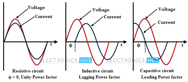
9) Leading and lagging current:
In energy measurement energy is basically power integrated over
time and power is basically voltage multiplied with current.
So, between voltage and current you need to select a reference.
Mostly voltage is taken as reference.
So only current leads or lags, not voltage as voltage is reference.
Remember the word CIVIL -> C IV means in
capacitive load ( C ) I leads V
VI L means in inductive load ( L ) I lags V.
Pretty easy haan
10) Doing some FFT
:
There are 2 domains in signal processing time domain and frequency
domain. The real world is time domain.
Imagine in live music performance, Tabla ( kind of Indian drum
) being low frequency and guitar being high frequency, can you tune your ear to
listen them separately ?? not possible right ?
Human ears have a range a of frequency 20 Hz to 20 kHz and
we hear that all.
So , time domain is very easy to understand just put time (
t ) on X axis and draw the signal. In time domain "shape" is most important.
Now , frequency domain , as this is frequency domain we are
not interested in shape of a signal , but we are interested in which different frequency signals
got mixed to generate this shape ???
So in frequency domain we are interested in different individual frequencies and their power values ( amplitude ).
To get these frequencies we do FFT.
There is something called Fourier transform , Discrete Fourier
transform in signal processing.
But FFT which is fast Fourier transform that is something we can do in
microcontroller, as it works on finite set of sample numbers and not on infinite
samples.
FFT is basically multiplying a unit signal of certain frequency
with a given signal to check if that signal is present in that signal or not.
If that signal in present we will get value otherwise zero.

11) Voltage , current sine wave formula :
V = Vmax sin ( 2*pi*f*t )
V = Imax sin ( 2*pi*f*t )
Basically “t” decides the shape of signal , everything else is
fixed , f, Vmax and Pi.
12 ) Power factor :
As we discussed earlier current mostly leads or lags the
voltage based on inductive or capacitive loads.
This difference of angle between voltage and current is phi.
If you take cosine it is called power factor.
Power factor is Cos(phi).
13) Current and power factor :
As voltage is our reference, current is I*cos(phi) . as it is already shifted with certain factor.
Remember full wave is 2*pi ( 360 ).
Ideal power factor is “1” so phi need to be “0” degree ,
means voltage is in sync with current.
14) Voltage measurement circuitry:
To measure voltage, you need to decrease the voltage to
bring in the range of ADC.
There are 2 method to do this: voltage transformer or resistor
divider. Voltage transformer provides isolations between input and output. But resistor
divider does not offer those isolation.
Most of the cheap multimeter uses register dividers. As voltage
transformer is bulky and expensive.
14) Current measurement circuitry:
For current measurement you need to bring current down using
a current transformer then use a shunt to convert this current into voltage ( V
= IR ) as our ADC only read voltage.
15) Types of Isolations:
if you want to separate your grounds you need to use certain
isolations.
Isolations can be either optical or Electromagnetic. Opto isolators are example of
optical isolation, a transformer is electromagnetic isolation.
16) Voltage translators:
When one of your device understands one voltage levels and
other device understand different voltage levels then you need voltage translators
to both can talk.
This are RS232 levels:
|
Data circuits |
Control circuits |
Voltage |
|
0 (space) |
Asserted |
+3 to +15 V |
|
1 (mark) |
Deasserted |
−15 to −3 V |
But for TTL levels +5V is logical 1 and 0V is logical 0. So, you need some voltage translator. Max232 is type of voltage translator.
17) Measuring DC voltage:
DC voltage measurement is very is easy you can take multiple
samples and take average , the more samples you can better the accuracy.
18) Measuring frequency:
Frequency = 1 / time period. So in AC signal you know your
sampling rate i,e time between two samples , then you know total samples
between two zero crossing . So you count total number of samples between two
zero crossing and calculate time period. Then do reciprocal of time-period this
will give you frequency.
19) Calibrating your measurements:
Calibrations are done based on straight line formula, so you
calculate 2 factors. offset factors and multiplier factor. Based on linearity of your measuring
instruments you might need multiple multiplier factors.
Besides this you might need to calibrate your power factor calculations
as well. (power factor calibration is little complex) , you need to read
rotation matrix for this :
< https://en.wikipedia.org/wiki/Rotation_matrix
>
20) Linearity of measurement:
Linearity depends upon many factors. But resistors are ideally considered linear and transformers have non-linearity in response. Besides this temperature also affects linearity.
